While working with embedded systems, we come across various moments where it is needed to observe a digital signal produced by a device. Some devices produce digital output through their GPIO pins to control various other peripheral devices. Meanwhile, there are sensors that produces digital output that can be read by a microcontroller/SoC. Furthermore, there are communication happening between multiple devices using digital protocols. Being able to observe any such digital signal helps to debug things when they are not functioning as expected. Although the obvious tool for observing signals is oscilloscope, there is a much better hardware device that is purpose-built for observing digital signals: logic analyser.
A logic analyser has a collection of input puts through which we can input digital signals. The device would read these pins and transfer the identified digital values to an attached computer. A specialised software running on the computer helps to visualise these data against time. Depending on the features of the software, it would be possible to decode a signal and take any usable data out in addition to simple observation of the signal. The Saleae Logic is such a logic analyser product that has multiple variants. I'm using the 8-channel version of the product that can be used to observe 8 digital signals at the same time. The device can be connected to a computer through the USB port. The host computer can run the official software application provided by the manufacturer, called Logic 2, which can be downloaded from their website (https://www.saleae.com/downloads).
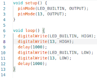
Let's explore how we can use Saleae Logic device to observe a signal. For this purpose, we are going to use an Arduino Uno device as the target device being observed. We are going to turn a digital output pin of the Arduino Uno to switch between high and low logic states by programming it to run a small code. So, program the Arduino Uno device to run the following code as the first step. This program is simply switching the pin 13 to HIGH and LOW states with a small time delay in between. Since there is a 1000 milliseconds (1 second) delay in between, we should be able to observe the digital output staying in HIGH and LOW states each 1 second time period.
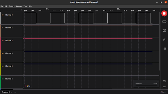
Once programmed, it is the time to observe the output using logic analyser. Connect the logic analyser to the computer through the USB port and launch the Logic 2 software on the computer. Connect the ground pin of the logic analyser to a ground pin of the Arduino Uno device. Then, let's connect first pin (pin 0) of the logic analyser to the pin 13 of the Arduino Uno. The following figure illustrates this wiring between the logic analyser and Arduino Uno devices. The logic analyser has nice clips that can be attached to jumper wires connected to Arduino Uno's pins. Now, powering up the Arduino Uno device should result in its digital pin 13 going high and low, which will be captured by the logic analyser and fed to the computer. The pin 13 value going high and low should be visible in Logic 2 software window in the specific channel --- channel 0 in this particular case. The following figure illustrates the signal observation on the Logic 2 software. It should be visible that the timing set by program code are very closely achieved by the Arduino Uno device.
Out of curiosity, I decided to attach the oscilloscope's probe to the ground and pin 13 of the Arduino Uno device to see how the digital signal is visualised on it. The following two figures show how the hardware wiring and the oscilloscope display looked like.
That's all for this blog post. Using logic analyser, let's explore how to intercept and understand digital communication protocols in some future blog posts.


Nice blogpost bro, there is a typo Its Arduino Uno not Aruino Uno. Congrats once again.
ReplyDeleteThanks! I corrected the typo now.
Delete